Design, Diagram, and Deploy a 3-tier Architecture Using AWS Console
Create a highly scalable architecture

The 3-Tier Architecture
As a popular implementation of client-server software design, the 3-tier architecture includes a presentation tier (web layer for the client), a logic tier (the application layer), and a data tier (containing a database layer).
Benefits:
- scalability — each item can scale horizontally, application servers can be deployed on multiple machines
- database integrity and security— the client cannot directly access the data with an application layer between them and the database
- improved performance — the presentation tier can cache requests, minimizing network utilization and load
- easier to maintain and modify — modifications or replacement of one tier does not affect the other tiers (decoupling), multiple developers can work on the different layers, reducing cost and time needed to integrate changes
Overview of Steps
- Create a VPC, subnets, internet gateway, and edit route tables.
- Create an application load balancer for the web tier (Internet-facing) and application tiers.
- Create the application and web tiers with EC2 auto-scaling groups. Configure security groups so the web tier only accepts traffic from the ALB (Application Load Balancer), and the application tier only accepts traffic from the web tier security group.
- Create the database tier using RDS (free tier).
- Verify the web tier can be accessed from the Internet and that it can ping the application tier.
Create a VPC
- In the AWS Management Console, navigate to VPC → Create VPC →VPC Settings → Resources to create → VPC only (include a name), IPV4 CIDR block →
10.0.0.0/16→ Create VPC - Subnets → Create subnet → VPC → VPC ID → select the VPC created in the previous step. Name each subnet and provide a CIDR for each. **Tip: Use an online subnet calculator like this one to determine CIDRs for each subnet.

4. Internet Gateway → create and name to allow the VPC’s public subnets traffic to the internet.

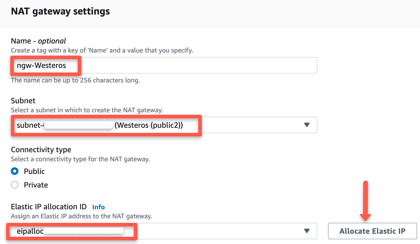
5. NAT Gateway: For this exercise, using a Network Address Translation (NAT) gateway with public access will allow instances in private subnets to connect to the internet, but will not allow unsolicited inbound connections. Since the application tier will contain instances in a private subnet, a NAT gateway is necessary to make sure that those instances can communicate with the web tier. Select NAT gateway from the VPC Dashboard → Create NAT gateway → Provide a name (optional), specify a public subnet and select Public for Connectivity type. Select “Allocate Elastic IP” to generate an IP address that will serve as a replacement for the source IP of the instances and translate addresses back to the source IPs.
6. Route Tables → Create two routing tables, one for the public subnets and one for the private subnets. Using the Routes tab →“Edit routes” for the public route table to make sure the route destinations are set to our CIDR block (10.0.0.0/16) and the Internet Gateway (0.0.0.0/0). For the private route table, the destinations should be set to our CIDR block (10.0.0.0/16) with the Target pointing to the NAT gateway we created.
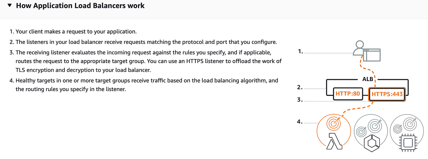
Create the Application Load Balancer
The Internet-facing Application Load Balancer provides an extra layer of security to keep clients from directly accessing EC2 instances in the web tier. An internal ALB will allow the web tier to communicate with the application tier that is deployed in private subnets.
- Navigate to
EC2 in the AWS Management Console. Load Balancing → Load Balancers → Create Load Balancer. Basic Configuration → Load balancer name (CityWatch) , Scheme →select “Internet-facing”, IP address type → select IPV4.Network mapping → VPC (select the one created in the previous section), Mappings → select each AZ and the public subnets associated with each.

4. Security groups → Create new security group (this will open a new tab)→ Basic details → Create a Security group name (KingsGuard), Description (allow public traffic to Internet) and select the VPC (Westeros) created earlier. Inbound rules must be configured to allow any IPV4 traffic through ports 80 (http) → Create security group
5. Listeners and routing → Listener should use the HTTP protocol on Port 80 → Create target group (this will open a new tab) → Choose a target type → Select Instances → create a Target group name (Andals) → accept all other defaults and click Next. Since we have not created the EC2 instances at this stage, we will skip Registering targets for now and Create target group. **Be sure to return to the Load Balancer page, select the new target group and Create load balancer.
** For the Internal ALB (Maesters), repeat the steps from above, using the private subnets (Westeros (private1) and Westeros (private2)) from each Availability Zone. The internal load balancer will be communicating between the web and application tiers, only receiving traffic from the internet-facing ALB. The application tier must be created before a Target group of instances can be registered with this ALB.
Configure Launch Templates and Auto Scaling Groups for the Web and App Tiers
- Web Tier: EC2 →
Instances → Launch Templates → Create launch template → create a Launch template name (MotherofDragons), Template version description (app tier), select the box underAuto Scaling guidance. AMI → Amazon Linux 2 Kernel 5.10 with a t2.micro Instance type. Create new key pair or select an existing key pair.Network Settings → do not specify a subnet in this template.Security groups → Create security group → Create a Security group name (TheUnsullied), Description (web-sg), VPC (Westeros) with rules to allow traffic through ports 80 (HTTP) and 22 (SSH). Under “Advanced network configuration”, I also selected “Auto-assign public IP”. To easily update all packages and install the “Apache” web server, I also added the following bootstrap under “User data” under “Advanced details” in the launch template before clicking “Create launch template”.
#!/bin/bash
yum update -y
yum install httpd -y
systemctl start httpd
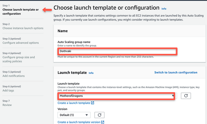
systemctl enable httpd2. Auto Scaling group for Web Tier: EC2 → Auto Scaling groups → Create Autoscaling group (Dothraki) using the “Launch template” created for the web tier (MotherofDragons). Continue to create the “auto-scaling group” for the web tier (see my other article to see how I accomplished this!).
In Step 3: “Configure advanced options”, however, I did select the optional step of attaching this group to my “Internet-facing Application Web Balancer”.


3. Application Tier: For this tier, since I did not have any code to run a true application, I repeated the steps for the web tier, but using the private subnets for the auto scaling group. I also configured the app security group by only allowing the web tier’s security group access.

Create the Database Tier and Verify Connectivity to Application Tier
- Navigate to “RDS” in the “AWS Management Console” → “Create database” → Select “Standard create” and select the following options to configure the database tier:
MySQL → Free tier → DB cluster identifier (FreeCities) → Master username (defaulted to admin) → Master password (specify and confirm) → Instance configuration → Burstable classes (db.t3.micro) → (continue with defaults until Connectivity). Select the correct VPC (Westeros) and create a new VPC security group (FacelessMen) and note that the 3306 port is added. Keep all other defaults and click “Create database”. Once the database is created, the VPC security group needs to be modified by deleting the default rule and selecting the database port 3306 and identifying the app tier’s security group as a source →Create rule.
- Note: To enable “Multi-AZ deployment” of an “RDS” instance, select a running RDS instance and click “Modify” → “Enable Multi-AZ deployment” and determine if a standby instance is needed (for production), and when you want to schedule the modification.

2. Return to “EC2” and locate one of the public instances ( — these have already been confirmed to have Internet connectivity as demonstrated in step 2 in the previous section of this article). In your local terminal, change directory using $ cd <name_of_directory> to make sure you are in the same directory as the keypair .pem file. If necessary, use the command $chmod 400 <nameofkeypair>.pem to secure it from being viewable. Then, log into one of the running public EC2 instances using the following command:
$ ssh -i "<nameofkeypair>.pem" ec2-user@<public_ip_of_instance>Test network connectivity by using the command below:
$ ping <ip_of_instance>I first tested this command using a public IP of my other web tier instance, receiving the following output:


Be sure to terminate instances by disabling the auto-scaling groups in “EC2”, terminate the “RDS” instance, and delete the “NAT gateways” created for the “VPC” in order avoid incurring charges.

