Synthwave Scene — My Coolest Three.js Project
A detailed walkthrough of my code
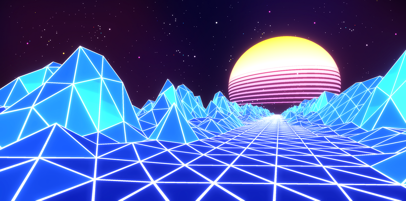
Approximately two years back there was a time when I was completely hooked to Retrowave/Synthwave music on YouTube. I really love the retro-futuristic aesthetics of both the music and the visuals — a forward-moving POV showing a super cool never-ending neon grid, with a setting sun just above the horizon. And since then I have always wanted to recreate a “Synthwave scene” using Three.js.
I remember having the first try at it last year, but I was stuck at some point, quickly felt frustrated, and finally gave up. To be honest, recreating the scene isn’t a trivial job, definitely not for a beginner. I’m pretty proud of myself to have finally created a decent Synthwave scene. Now, I’m going to walk you through the process to create the same scene step-by-step.
Let’s start with the breakdown.
Tutorial Breakdown
- Live Demo
- Approaches to building the terrain
- Code structure of the project
- Set up the scene environment
- Set up the plane geometry for the terrain ⛰
- Create the bright/neon grid lines on the terrain
- Create the illusion of a never-ending terrain
- Add the setting sun ☀ and animate it
- Add GUI controls to tweak params during runtime
- Post-process the scene with Bloom effect to make it look way cooler!
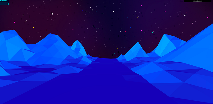
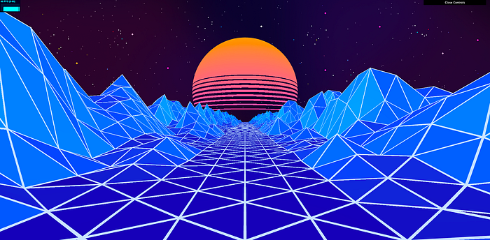
1. Live Demo
As usual, take a first look at what you’re gonna build! This demo is hosted on my code sandbox account. It looks nicer and less blocky in a larger window.
Pretty cool scene huh?
If you want to see the full code, check out https://github.com/franky-adl/threejs-synthwave-scene.
2. Approaches to building the terrain
This section explains how to approach the problems encountered during the making of the terrain geometry which really helps you understand my thinking processes behind the scenes. This will get a bit long, so if you feel like diving into code right away, skip to the next section.
The first hurdle to overcome in making a synthwave scene is generating the terrain. We’re going to make a terrain that is flat at the center which makes the road, and bumpy on the sides which makes the mountains. There are different ways to generate the terrain; some seem easier in your head but harder when you try coding it. And to go deeper into the terrain problem, there are actually three major questions:
A. What kind of geometry should we use?
B. How to make the terrain flat at the center but bumpy on the sides?
C. How to animate the terrain to fake an endless road effect?
Let’s go through them one-by-one.
A. What kind of geometry should we use?
At first glance, you might think PlaneGeometry is the obvious option; well it is but not without some twists. There’s an important point to bear in mind: the neon lines have to match the wireframe of this plane geometry; say if the neon lines do not trace the diagonal lines in your PlaneGeometrygrid, you would see adjacent triangular faces where the shading changes across the diagonal, but without a line to cut off that shading change, the visuals would look odd. So if you use vanillaPlaneGeometry as the terrain’s base geometry, your neon lines will also need to trace all the diagonals besides the vertical and horizontal grid lines, with the downside of making the central pathway look asymmetric.
If we want to avoid the diagonal lines problem, there are 3 options.
- Rotate the whole
PlaneGeometryby 45 degrees! - Make a custom
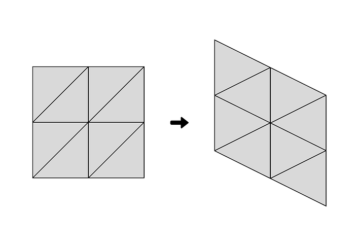
BufferGeometrythat is a tessellation of rotated squares. - Shear the
PlaneGeometryin y-direction until you have a tessellation of symmetric triangles!


matrix.makeShear(), with xy set to -0.5You might say hey there’s option 4, which is to simply use a square grid! Sadly that isn’t a viable option because ultimately the triangle is the basic building block of Three.js; there’s no way that I know of can stack a grid with pure squares.
So let’s consider the 3 options. Remember we need to pave a long road in the terrain so potentially we need to duplicate and join up the planes in order to make it longer.
- For option 1, joining up multiple rotated planes from head-to-toe poses an obvious problem: there will be large empty spaces between them on the sides. It would be quite painful and inefficient to tessellate a forward-pointing rhombus into a road.
- For option 2, the custom geometry looks nice but the overhead is too high; you would have to calculate and set up the positions of the vertices yourself, and joining the planes up precisely is more complicated.
- For option 3, it only takes 2–3 more lines of code to shear it until the triangle-pairs are symmetric. Overhead is minimal. Although the whole plane is stretched diagonally, it is still easy to multiply and join the planes up, and the viewer wouldn’t notice the shear if we set up the camera and the animation loop correctly.
Option 3 is the winner 👑!
B. How to make the terrain flat at the center but bumpy on the sides?
First thing we need is a heightmap image. Whether you do it by hand or by some generative code, it should be a black-and-white image, where the white means highest and black means the lowest. I generated mine using radial gradients and texture brushes in Affinity Designer. Apparently, we need to keep the central vertical rectangular area black to pave it as the road.

The next problem is to get our plane geometry to be rendered with the height data from this heightmap. First thing I tried was to load the heightmap image using TextureLoader, then assign the texture to the displacementMap property of a MeshStandardMaterial. But this method wouldn’t work for the neon lines to be later created(i will explain why in the section for neon lines) because the displacementMap property only updates vertex positions in the vertexShader program during runtime, the positions array of the plane geometry object in our main js program is unaffected.
Thus I had to manually extract the greyscale values from the displacement map image, scale it and assign its value directly to each vertex’s z position value of our geometry object. I found out that we don’t even need to calculate the normals manually, the lighting just works somehow!
C. How to animate the terrain to fake an endless road effect?
This problem exists in many games/animations that need some kind of endless road. I’m sure it is solved many times over and over. Yes, the problem by itself is simple to solve, but in our situation, there’s an extra complication(will explain in the next paragraph). The big picture is still the same; assuming we have multiple plane instances joined up to form our road, we speed them up towards the camera like a train so that it looks like we’re moving forward instead from the camera’s perspective. As soon as the headpiece of the train is behind our camera, we set its position back at the tail of the train, and that is how to make our road look endless.
The extra issue is how do we make sure the plane instances are joined perfectly at their conjunctions without gaps. Imagine using the same heightmap for all of the plane instances, the top row of pixels of the heightmap most likely don’t match with the bottom row pixels, and naturally, you would see gaps like this:
The solution is actually quite easy. You could edit your heightmap image, copy the top row pixels and paste it on top of the bottom row pixels. That works.
But I prefer a programmatic way because if you want to switch between heightmap images, the program automatically does the perfect stitch-up for you so that you don’t have to do the stitch work yourself every time you want to try a new heightmap.
3. Code structure of the project
I started this project off of my custom starter template, hosted publicly at https://github.com/franky-adl/threejs-starter-template. This tutorial is written with the assumption that you start the project with this starter template.
Of course, you can use any boilerplate or setup you’re comfortable with, you’ll then have to do some minor code translations to make my code work for your setup. For more details on how this starter template works, you can read my previous article here.
Now, let me give you a brief overview of how the code is structured.
The project files hierarchy:
.
├── src
│   └── assets
│       ├── heightmap.png
│       └── Starfield.png
│   ├── common-utils.js
│   ├── core-utils.js
│   ├── functions.js
│   ├── index.html
│   └── index.js
├── .gitignore
├── package-lock.json
└── package.json
All our code and images are basically within the src folder. In the package.json, we only have 3 dependencies:
three@0.145.0: the Three.js librarydat.gui@0.7.9: the gui controls libraryparcel@2.7.0: the bundler tool
In src, store all the textures/images under the assets sub-folder.
The file that contains most of our scene-building code is the index.js file.
The core-utils.js contains some convenient methods that set up the common objects needed in most Three.js projects (i.e. camera, renderer, composer, window resize listener, mouse onmove listener, animation loop).
The common-utils.js has some more convenient methods that I myself find useful across Three.js projects(e.g. image loading function with async/await support, hex to rgb convertor, etc…).
The functions.js contains functions used in this project that helps take part of the code away from the main js file to make it more readable and less bulky.
The index.html is the entrypoint for the parcel bundler, which has a script tag that requests the index.js file.
4. Set up the scene environment
Let’s assume we start off this project using my threejs-starter-template. Running the following commands would open up a tab showing you a spinning torus behind some light boxes.
git clone https://github.com/franky-adl/threejs-starter-template
cd threejs-starter-template
npm i
npm run start
Rename the project name threejs-starter-template in various places to your liking. The objects in the scene are just for demonstration, we need to remove them so that we can start anew.
To clean up, and replace contents ofindex.jswith the following code:
// ThreeJS and Third-party deps
import * as THREE from "three"
import * as dat from 'dat.gui'
import Stats from "three/examples/jsm/libs/stats.module"
import { OrbitControls } from "three/examples/jsm/controls/OrbitControls"

// Core boilerplate code deps
import { createCamera, createComposer, createRenderer, runApp } from "./core-utils"

global.THREE = THREE

/**************************************************
 * 0. Tweakable parameters for the scene
 *************************************************/
const params = {
  // general scene params
}


/**************************************************
 * 1. Initialize core threejs components
 *************************************************/
// Create the scene
let scene = new THREE.Scene()

// Create the renderer via 'createRenderer',
// 1st param receives additional WebGLRenderer properties
// 2nd param receives a custom callback to further configure the renderer
let renderer = createRenderer({ antialias: true })

// Create the camera
// Pass in fov, near, far and camera position respectively
let camera = createCamera(45, 1, 1000, { x: 0, y: 5, z: -15 })

// The RenderPass is already created in 'createComposer'
let composer = createComposer(renderer, scene, camera, (comp) => {
})

/**************************************************
 * 2. Build your scene in this threejs app
 * This app object needs to consist of at least the async initScene() function (it is async so the animate function can wait for initScene() to finish before being called)
 * initScene() is called after a basic threejs environment has been set up, you can add objects/lighting to you scene in initScene()
 * if your app needs to animate things(i.e. not static), include a updateScene(interval, elapsed) function in the app as well
 *************************************************/
let app = {
  async initScene() {
    // OrbitControls
    this.controls = new OrbitControls(camera, renderer.domElement)
    this.controls.enableDamping = true

    // GUI controls
    const gui = new dat.GUI()

    // Stats - show fps
    this.stats1 = new Stats()
    this.stats1.showPanel(0) // Panel 0 = fps
    this.stats1.domElement.style.cssText = "position:absolute;top:0px;left:0px;"
    // this.container is the parent DOM element of the threejs canvas element
    this.container.appendChild(this.stats1.domElement)
  },
  // @param {number} interval - time elapsed between 2 frames
  // @param {number} elapsed - total time elapsed since app start
  updateScene(interval, elapsed) {
    this.controls.update()
    this.stats1.update()
  }
}

/**************************************************
 * 3. Run the app
 * 'runApp' will do most of the boilerplate setup code for you:
 * e.g. HTML container, window resize listener, mouse move/touch listener for shader uniforms, THREE.Clock() for animation
 * Executing this line puts everything together and runs the app
 * ps. if you don't use custom shaders, pass undefined to the 'uniforms'(2nd-last) param
 * ps. if you don't use post-processing, pass undefined to the 'composer'(last) param
 *************************************************/
runApp(app, scene, renderer, camera, true, undefined, composer)
Then, remove the checker_tile.png from the assets folder.
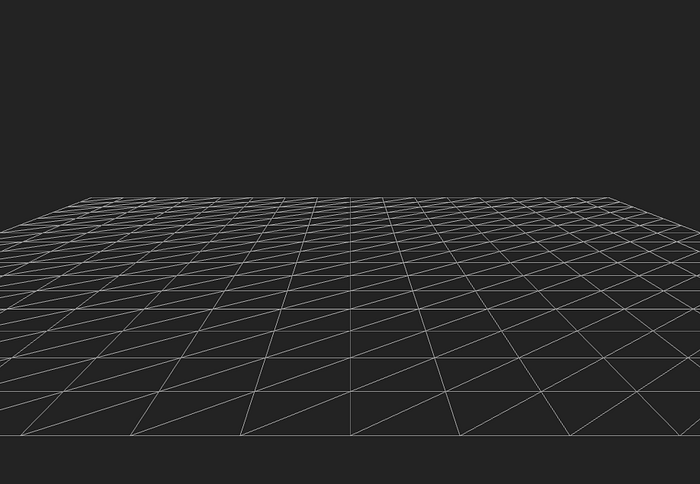
Now running npm run start should give you a black screen with just the fps counter at the top-left. Saving code changes on the files from now on will trigger the parcel bundler to auto-rebuild and your Three.js browser tab will auto-refresh.
% npm run start
> threejs-synthwave-scene@1.0.0 start
> parcel src/index.html --open
Server running at http://localhost:1234
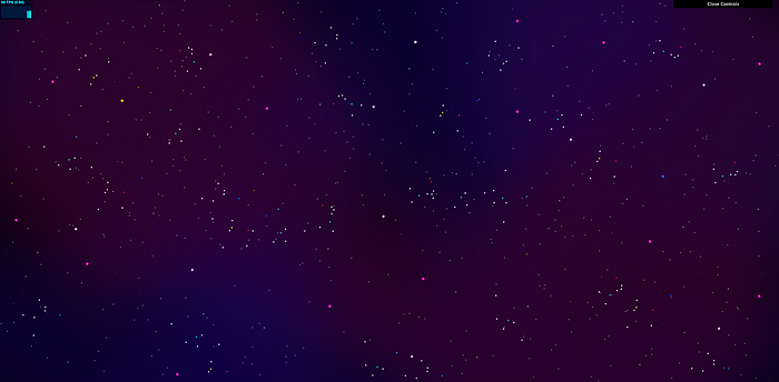
✨ Built in 1.21sLet’s put in a background image to start with!
Copy the Starfield.png from my synthwave repo to the assets folder.
Create a new file functions.js with the following contents:
import { maintainBgAspect } from "./common-utils"

/**
 * @param {object} scene the Three.js scene object
 * @param {object} image the path to the background image
 * @returns a Promise that resolves after the texture is loaded as the scene's background
 */
export const loadSceneBackground = (scene, image) => {
  return new Promise((resolve, reject) => {
    var loader = new THREE.TextureLoader();
    loader.load(image, function (texture) {
      scene.background = texture
      // position scene background such that image aspect ratio is preserved
      maintainBgAspect(scene, texture.image.width, texture.image.height)
      // need to maintain background aspect ratio across window resizes
      window.addEventListener("resize", () => {
        maintainBgAspect(scene, texture.image.width, texture.image.height)
      })
      resolve()
    }, undefined, function (error) {
      console.log(error)
      reject(error)
    });
  })
}
We wrap the TextureLoader.load() function’s callback with a Promise so that we can use the await expression on loadSceneBackground within our async initScene() function.
We want this Promise to be resolved only when the texture is loaded, that’s why we call resolve() in the onLoad callback passed to loader.load(). This ensures our scene is only unveiled after the background is fully loaded. This unveiling mechanism works because of this code in the runApp() function in core-utils.js:
app.initScene().then(() => {
  const veil = document.getElementById("veil")
  veil.style.opacity = 0
  return true
})
With the background loading function in place, we need to execute it in our main program.
Make the following code changes to index.js:
+ import { loadSceneBackground } from "./functions"
+ import Background from "./assets/Starfield.png"
...
let app = {
async initScene() {
// OrbitControls
this.controls = new OrbitControls(camera, renderer.domElement)
this.controls.enableDamping = true
+ // Environment
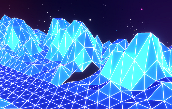
+ await loadSceneBackground(scene, Background)Now we have a starry night sky! Nice and easy.
5. Set up the plane geometry for the terrain ⛰
First, copy the heightmap.png from my synthwave repo to the assets folder.
Next, append the following code into common-utils.js:
/**
 * This loadImage function returns a Promise that is resolved when the image finishes loading
 * if you use it with await, it returns the loaded image object
 * @param {string} path image file path
 * @returns a Promise that resolves with the value assigned as the loaded image
 */
export const loadImage = (path) => {
    return new Promise((resolve, reject) => {
        const img = new Image()
        img.crossOrigin = "Anonymous" // to avoid CORS if used with Canvas
        img.src = path
        img.onload = () => {
            resolve(img)
        }
        img.onerror = (e) => {
            reject(e)
        }
    })
}
We will use this function to load our heightmap synchronously.
Then, append the following code into functions.js :
/**
 * original reference: https://gist.github.com/jawdatls/465d82f2158e1c4ce161
 * This function lets you get the greyscale color value from a specific point in an image
 * In this scenario, we pass in a displacement map as imageData,
 * and u/v values which gets translated to a certain point on the image
 * getting either one of r/g/b value as the displacement value is the same
 * since the image is supposed to be black and white
 * note that the direction of v axis in texture data is the inverse of the y axis in image data
 *
 * @param {object} imageData the color data of the displacement map image to be passed in
 * @param {number} u the x position [0,1] of the target pixel
 * @param {number} v the y position [0,1] of the target pixel
 * @param {number} cvWidth the width of the heightmap image in canvas
 * @param {number} cvHeight the height of the heightmap image in canvas
 * @returns {number} height value of the requested point within [0,5]
 */
export function getZFromImageDataPoint(imageData, u, v, cvWidth, cvHeight) {
  const mapWidth = cvWidth
  const mapHeight = cvHeight
  const displacementScale = 5
  var x = Math.round(u * (mapWidth - 1))
  var y = Math.round((1 - v) * (mapHeight - 1))
  var index = (y * imageData.width + x) * 4
  var red = imageData.data[index]
  return red / 255 * displacementScale
}
We will use this function to extract the height values of corresponding pixels for each plane vertex from the heightmap.png.
The u and v inputs for this function are exactly the uv values of the plane vertices. The function translates the uv coordinates into image coordinates.
For this line of codevar index = (y * imageData.width + x) * 4, y and x are the mapped row and column numbers in the image data, multiplying that by 4 is because imageData.data stores color values for all pixels sequentially (i.e. [r,g,b,a, r,g,b,a, …]).
Thus the resulting index is the first color channel for each pixel, which is red. It doesn’t matter which color channel we get as the heightmap is black and white.
Finally, we magnify the value by a suitable scale of 5. The returned value from this function is thus within the range of [0, 5].
Let’s make the following code changes in index.js:
+ import { loadImage } from "./common-utils"
- import { loadSceneBackground } from "./functions"
+ import { loadSceneBackground, getZFromImageDataPoint } from "./functions"
import Background from "./assets/Starfield.png"
+ import HeightMap from "./assets/heightmap.png"

global.THREE = THREE

/**************************************************
 * 0. Tweakable parameters for the scene
 *************************************************/
const params = {
  // general scene params
+ dirLightColor1: 0x2dd7ff,
+ dirLightColor2: 0x2dd7ff,
+ // plane params
+ metalness: 0.2,
+ roughness: 0.7,
+ meshColor: 0xffffff,
+ meshEmissive: 0x000098,
}
+ const terrainWidth = 30
+ const terrainHeight = 30
+ const lightPos1 = {
+   x: 15,
+   y: 1,
+   z: 5
+ }
+ const lightIntensity1 = 0.85
+ const lightPos2 = {
+   x: -15,
+   y: 1,
+   z: 5
+ }
+ const lightIntensity2 = 0.85

...

- let camera = createCamera(45, 1, 1000, { x: 0, y: 5, z: -15 })
+ let camera = createCamera(70, 1, 120, { x: 0, y: 0, z: 2.4 })

...

let app = {
  async initScene() {
    // OrbitControls
    this.controls = new OrbitControls(camera, renderer.domElement)
    this.controls.enableDamping = true

    // Environment
    await loadSceneBackground(scene, Background)

+   // Lighting
+   this.dirLight1 = new THREE.DirectionalLight(params.dirLightColor1, lightIntensity1)
+   this.dirLight1.position.set(lightPos1.x, lightPos1.y, lightPos1.z)
+   scene.add(this.dirLight1)
+   this.dirLight2 = new THREE.DirectionalLight(params.dirLightColor2, lightIntensity2)
+   this.dirLight2.position.set(lightPos2.x, lightPos2.y, lightPos2.z)
+   scene.add(this.dirLight2)

+   // load heightmap to a new image first, then read its color data to set the heights of our plane vertices
+   // see: https://gist.github.com/jawdatls/465d82f2158e1c4ce161
+   let hm_image = await loadImage(HeightMap)
+   var canvas = document.createElement("canvas")
+   canvas.width = hm_image.width
+   canvas.height = hm_image.height
+   var context = canvas.getContext("2d")
+   context.drawImage(hm_image, 0, 0)
+   var hm_imageData = context.getImageData(0, 0, canvas.width, canvas.height)

+   // Create a PlaneGeom
+   let planeGeometry = new THREE.PlaneGeometry(terrainWidth, terrainHeight, terrainWidth, terrainHeight)
+   let geometryPositions = planeGeometry.getAttribute("position").array
+   let geometryUVs = planeGeometry.getAttribute("uv").array

+   // update each vertex position's z value according to the value we extracted from the heightmap image
+   for (let index = 0; index < geometryUVs.length / 2; index++) {
+     let vertexU = geometryUVs[index * 2]
+     let vertexV = geometryUVs[index * 2 + 1]
+     // Update the z positions according to height map
+     let terrainHeight = getZFromImageDataPoint(hm_imageData, vertexU, vertexV, canvas.width, canvas.height)
+     geometryPositions[index * 3 + 2] = terrainHeight
+   }
+   // skew the plane geometry
+   const shearMtx = new THREE.Matrix4()
+   shearMtx.makeShear(-0.5, 0, 0, 0, 0, 0)
+   planeGeometry.applyMatrix4(shearMtx)

+   // material for the plane geometry
+   let meshMaterial = new THREE.MeshStandardMaterial({
+     color: new THREE.Color(params.meshColor),
+     emissive: new THREE.Color(params.meshEmissive),
+     metalness: params.metalness,
+     roughness: params.roughness,
+     flatShading: true
+   })

+   // create plane mesh and add to scene
+   let mesh = new THREE.Mesh(planeGeometry, meshMaterial)
+   mesh.position.set(0, -1.5, 0)
+   mesh.rotation.x -= Math.PI / 2
+   scene.add(mesh)

    // GUI controls
    const gui = new dat.GUI()
So what’s that all about? First, we’re adding the dependencies and the necessary variables to be used in setting up the lighting and plane geometry + material. We also update the camera to better view our scene; I like using a larger fov so that the scene looks wider.
Then in the initScene(), we add in two DirectionalLight positioned to shine onto both left and right mountain sides. Without light, the whole terrain would have the same color with no shading variance.
Afterward, we create a canvas object to store the loaded heightmap image, and save the image data into hm_imageData via context.getImageData(). Don’t worry, this canvas isn’t added to the document and thus isn’t visible on the screen.
Then we create a square planeGeometry with the same width and height(set as 30), also same values for width/height segments for simplicity. We extract the position and uv arrays out of the BufferAttribute from the vanilla PlaneGeometry for later use.
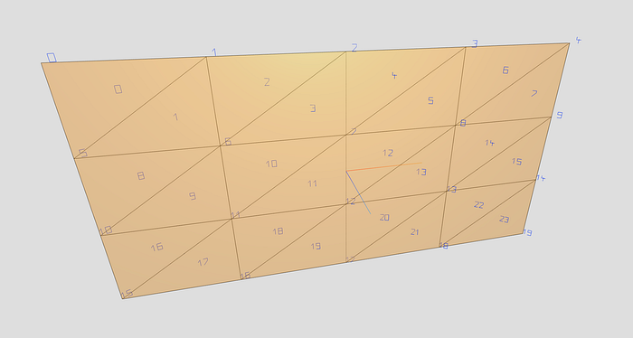
Then we loop through all the vertices to set the height value for each vertex. We use getZFromImageDataPoint() to get the corresponding height value for each vertex on the heightmap. Looking at the for loop,geometryUVs.length / 2 means total number of vertices because the BufferAttribute arrays store the values sequentially in a single level instead of nesting the x,y,z or u,v values of each vertex; see the image below.
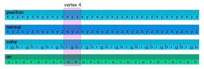
That’s why in geometryPositions[index * 3 + 2], we times 3 as each vertex has 3 position values x, y and z, adding by 2 means getting the z value.
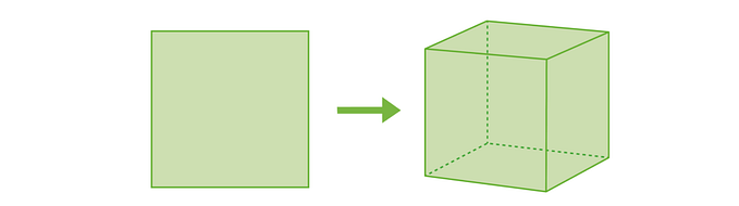
Now we got the heights set up correctly for each vertex, we still need to shear the plane along the y-direction. I didn’t really dive into the source code of the makeShear function but if I’m not mistaken, shearing it by 0.5 should be the correct magnitude.
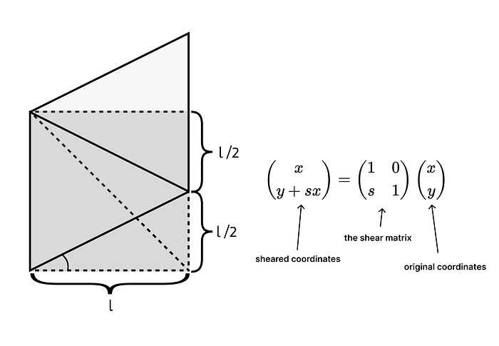
The vanilla plane geometry we created consisted of squares since the width and height values are the same as width and height segments. We want to shear it in the y-direction by half the length of the square l/2. Looking at the simplified 2d shearing equation above, if we set the shear factor s to 0.5, then our resulting coordinates would be (x, y + 0.5x). Substituting x = l, the sheared amount would be l/2 and that’s exactly the amount we want.
This video explains the shearing concept pretty well.
For the plane material we use MeshStandardMaterial so we can tweak with metalness and roughness. Turning flatShading on is important because the visual style is more fitting for objects in low-poly.
After applying all the changes, your scene should now look like this:
6. Create the bright/neon grid lines on the terrain
Initially, I tried using WireframeGeometry with LineSegments to create the grid lines but there’s a serious limitation. The LineBasicMaterial used is sadly limited to have linewidth always at 1 regardless of what value is set.
Luckily, there’s another way to implement lines with configurable thickness. Following the method demonstrated by this example, we’re able to control the thickness of the lines. But if we’re to implement this method, we’ll require the plane geometry’s vertices positions with its heightmap data infused.
That’s why need to manually calculate the z value for each vertex instead of simply assign the heightmap to the material’s displacementMap property (as explained in section 2).
Make the following changes in index.js:
import Stats from "three/examples/jsm/libs/stats.module"
import { OrbitControls } from "three/examples/jsm/controls/OrbitControls"
+ import { LineGeometry } from "three/examples/jsm/lines/LineGeometry"
+ import { LineMaterial } from "three/examples/jsm/lines/LineMaterial"
+ import { Line2 } from "three/examples/jsm/lines/Line2"

...

const params = {
  // general scene params
  dirLightColor1: 0x2dd7ff,
  dirLightColor2: 0x2dd7ff,
  // plane params
  metalness: 0.2,
  roughness: 0.7,
  meshColor: 0xffffff,
  meshEmissive: 0x000098,
+ lineWidth: 0.04,
+ lineColor: 0xcee4ff,
}

...

- let renderer = createRenderer({ antialias: true }, (_renderer) => {
+ let renderer = createRenderer({ antialias: true, logarithmicDepthBuffer: true }, (_renderer) => {

...

let app = {
  async initScene() {
    ...

+   // the grid lines, reference: https://threejs.org/examples/?q=line#webgl_lines_fat
+   let lineGeometry = new LineGeometry()
+   let linePositions = []
+   // This is a specific way to map line points to cooresponding vertices of the planeGeometry
+   for (let row = 0; row < terrainHeight; row++) {
+     let isEvenRow = row % 2 == 0
+     for (let col = (isEvenRow ? 0 : (terrainWidth - 1)); isEvenRow ? (col < terrainWidth) : (col >= 0); isEvenRow ? col++ : col--) {
+       for (let point = (isEvenRow ? 0 : 3); isEvenRow ? (point < 4) : (point >= 0); isEvenRow ? point++ : point--) {
+         let mappedIndex
+         let rowOffset = row * (terrainWidth + 1)
+         if (point < 2) {
+           mappedIndex = rowOffset + col + point
+         } else {
+           mappedIndex = rowOffset + col + point + terrainWidth - 1
+         }

+         linePositions.push(geometryPositions[mappedIndex * 3])
+         linePositions.push(geometryPositions[mappedIndex * 3 + 1])
+         linePositions.push(geometryPositions[mappedIndex * 3 + 2])
+       }
+     }
+   }
+   lineGeometry.setPositions(linePositions)

+   // the material for the grid lines
+   let lineMaterial = new LineMaterial({
+     color: params.lineColor,
+     linewidth: params.lineWidth, // in world units with size attenuation, pixels otherwise
+     alphaToCoverage: false,
+     worldUnits: true // such that line width depends on world distance
+   })

    // create plane mesh and add to scene
    let mesh = new THREE.Mesh(planeGeometry, meshMaterial)
    mesh.position.set(0, -1.5, 0)
    mesh.rotation.x -= Math.PI / 2
    scene.add(mesh)

+   // create the lines mesh and add to scene
+   let line = new Line2(lineGeometry, lineMaterial)
+   line.computeLineDistances()
+   line.position.set(0, -1.5, 0)
+   line.rotation.x -= Math.PI / 2
+   scene.add(line)

    // GUI controls
    const gui = new dat.GUI()
Notice that we turn on the logarithmicDepthBuffer for the renderer. This configuration fixes the z-fighting issue between the grid lines and the plane geometry. Read more about this issue in the lower half of https://threejs.org/manual/#en/cameras.
Also, notice that the LineGeometry, LineMaterial and Line2 classes are not from the core Three.js library. They are imported from the jsm folder.
The way LineGeometry works is it requires a sequential array of vertices positions, then it will draw the line to link up the points designated in the positions array in the same sequential order. So basically only a single line is drawn, from start to end.
What the tri-nested for loops code block is doing is setting up that sequential array of vertices correctly. I’ll explain with a quick example.
Say if we don’t calculate linePositions at all and use geometryPositions of the plane geometry directly:
lineGeometry.setPositions(geometryPositions)What you see would be chaotic:
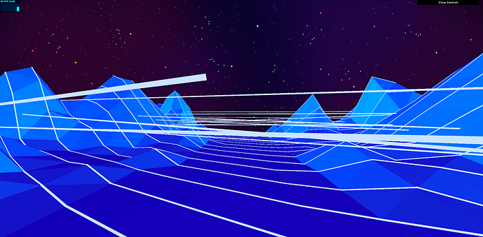
The reason is that the default ordering of the vertices' positions is row-by-row, from left to right. See the plane geometry with number helpers that label each vertex below:
Thus, the line being drawn is simply following the vertex order which results in this(the blue line):
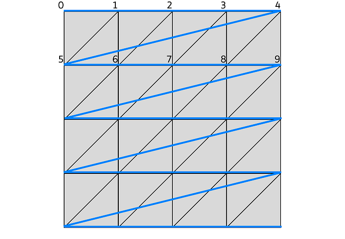
In order to prevent the line jumping from right edge to the left edge, we’ll have to order the line positions in a particular way.
For the first row, we should draw the line following this vertex order:
v0 — v1 — v5 — v6, followed by v1 — v2 — v6 — v7, and so on.
For the second row, however, we’ll have to start from the right-hand side instead of the left-hand side because otherwise, we’ll have the same problem of the line jumping from right edge to left edge. So basically, for even rows, we’ll have to order the vertices in a reversed sequence of the odd rows.
Thus for the second row, we should follow this vertex order:
v14 — v13 — v9 — v8, followed by v13 — v12 — v8 — v7, and so on.
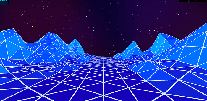
By implementing this particular ordering, we can get a perfect line grid sitting on top of our terrain:
7. Create the illusion of a never-ending terrain
Here comes the exciting part of the project: faking a never-ending terrain!
In case you’ve skipped the explanation in section 2 above, I’ll quickly recap the concept:
- make a couple sets of the terrain
- join them up like a train
- animate the train towards the camera
- pop the train head and put it back to its tail if it goes behind the camera.
- Voila! That’s how you fake an endless terrain.
During my development, I found that repeating just one heightmap for all the consecutive terrain clones was visually too repetitive, so I made a quick fix to make the terrain look less repetitive; “create” a second heightmap by inverting the heightmap horizontally. That is to use the heightmap as is for “odd” terrains, and inverse the heightmap for “even” terrains.
Let’s make the following code changes in index.js:
/**************************************************
 * 0. Tweakable parameters for the scene
 *************************************************/
const params = {
  // general scene params
+ speed: 2.5,

...

const lightIntensity2 = 0.85
+ // need to be even number since the consecutive terrains are stitched in pairs
+ const numOfMeshSets = 6

...

let app = {
  async initScene() {
    ...
    scene.add(this.dirLight2)

+   // create sets of objects, for the capability to use different heightmaps for each set of plane and lines
+   let planeGeometries = []
+   let lineGeometries = []
+   let geometryPositionsArray = []

+   // we only loop twice here, although we load a single HeightMap, the trick is:
+   // first loop we load the HeightMap the normal way
+   // second loop we load the HeightMap data horizontally inversed
+   for (let i = 0; i < 2; i++) {
      // load heightmap to a new image first, then read its color data to set the heights of our plane vertices
      // see: https://gist.github.com/jawdatls/465d82f2158e1c4ce161
      let hm_image = await loadImage(HeightMap)
      var canvas = document.createElement("canvas")
      canvas.width = hm_image.width
      canvas.height = hm_image.height
      var context = canvas.getContext("2d")
      context.drawImage(hm_image, 0, 0)
      var hm_imageData = context.getImageData(0, 0, canvas.width, canvas.height)

      // Create a PlaneGeom
      let planeGeometry = new THREE.PlaneGeometry(terrainWidth, terrainHeight, terrainWidth, terrainHeight)
      let geometryPositions = planeGeometry.getAttribute("position").array
      let geometryUVs = planeGeometry.getAttribute("uv").array

      // update each vertex position's z value according to the value we extracted from the heightmap image
      for (let index = 0; index < geometryUVs.length / 2; index++) {
        let vertexU = geometryUVs[index * 2]
        let vertexV = geometryUVs[index * 2 + 1]
-       // Update the z positions according to height map,
-       let terrainHeight = getZFromImageDataPoint(hm_imageData, vertexU, vertexV, canvas.width, canvas.height)
+       // Update the z positions according to height map, inverse heightmap horizontally for the second loop
+       let terrainHeight = getZFromImageDataPoint(hm_imageData, (i == 0 ? vertexU : 1 - vertexU), vertexV, canvas.width, canvas.height)
        geometryPositions[index * 3 + 2] = terrainHeight
      }
      // skew the plane geometry
      const shearMtx = new THREE.Matrix4()
      shearMtx.makeShear(-0.5, 0, 0, 0, 0, 0)
      planeGeometry.applyMatrix4(shearMtx)

+     planeGeometries.push(planeGeometry)
+     geometryPositionsArray.push(geometryPositions)
+   }

+   // zip up the gaps between the 1st and 2nd plane geometries
+   for (let index = 0; index <= terrainWidth; index++) {
+     let bottomOffset = (terrainWidth + 1) * terrainHeight
+     // 2nd geom's bottom row height should be synced with 1st geom's top
+     geometryPositionsArray[1][(bottomOffset + index) * 3 + 2] = geometryPositionsArray[0][index * 3 + 2]
+     // 1st geom's bottom row height should be synced with 2nd geom's top
+     geometryPositionsArray[0][(bottomOffset + index) * 3 + 2] = geometryPositionsArray[1][index * 3 + 2]
+   }

    // material for the plane geometry
    let meshMaterial = new THREE.MeshStandardMaterial({
      color: new THREE.Color(params.meshColor),
      emissive: new THREE.Color(params.meshEmissive),
      metalness: params.metalness,
      roughness: params.roughness,
      flatShading: true
    })

    // the grid lines, reference: https://threejs.org/examples/?q=line#webgl_lines_fat
+   for (let i = 0; i < 2; i++) {
      let lineGeometry = new LineGeometry()
      let linePositions = []
      // This is a specific way to map line points to corresponding vertices of the planeGeometry
      for (let row = 0; row < terrainHeight; row++) {
        let isEvenRow = row % 2 == 0
        for (let col = (isEvenRow ? 0 : (terrainWidth - 1)); isEvenRow ? (col < terrainWidth) : (col >= 0); isEvenRow ? col++ : col--) {
          for (let point = (isEvenRow ? 0 : 3); isEvenRow ? (point < 4) : (point >= 0); isEvenRow ? point++ : point--) {
            let mappedIndex
            let rowOffset = row * (terrainWidth + 1)
            if (point < 2) {
              mappedIndex = rowOffset + col + point
            } else {
              mappedIndex = rowOffset + col + point + terrainWidth - 1
            }

-           linePositions.push(geometryPositions[mappedIndex * 3])
-           linePositions.push(geometryPositions[mappedIndex * 3 + 1])
-           linePositions.push(geometryPositions[mappedIndex * 3 + 2])
+           linePositions.push(geometryPositionsArray[i][mappedIndex * 3])
+           linePositions.push(geometryPositionsArray[i][mappedIndex * 3 + 1])
+           linePositions.push(geometryPositionsArray[i][mappedIndex * 3 + 2])
          }
        }
      }
      lineGeometry.setPositions(linePositions)

+     lineGeometries.push(lineGeometry)
+   }

-   // create plane mesh and add to scene
-   let mesh = new THREE.Mesh(planeGeometry, meshMaterial)
-   mesh.position.set(0, -1.5, 0)
-   mesh.rotation.x -= Math.PI / 2
-   scene.add(mesh)
-   // create the lines mesh and add to scene
-   let line = new Line2(lineGeometry, lineMaterial)
-   line.computeLineDistances()
-   line.position.set(0, -1.5, 0)
-   line.rotation.x -= Math.PI / 2
-   scene.add(line)

+   this.meshGroup = []
+   this.lineGroup = []
+   // create multiple sets of plane and line meshes determined by numOfMeshSets
+   for (let i = 0; i < numOfMeshSets; i++) {
+     // create the meshes
+     let mesh = new THREE.Mesh(planeGeometries[i % 2], meshMaterial)
+     let line = new Line2(lineGeometries[i % 2], lineMaterial)
+     line.computeLineDistances()
+     // set the correct pos and rot for both the terrain and its wireframe
+     mesh.position.set(0, -1.5, -terrainHeight * i)
+     mesh.rotation.x -= Math.PI / 2
+     line.position.set(0, -1.5, -terrainHeight * i)
+     line.rotation.x -= Math.PI / 2
+     // add the meshes to the scene
+     scene.add(mesh)
+     scene.add(line)
+     this.meshGroup.push(mesh)
+     this.lineGroup.push(line)
+   }

...

  // @param {number} interval - time elapsed between 2 frames
  // @param {number} elapsed - total time elapsed since app start
  updateScene(interval, elapsed) {
    this.controls.update()
    this.stats1.update()

+   for (let i = 0; i < numOfMeshSets; i++) {
+     this.meshGroup[i].position.z += interval * params.speed
+     this.lineGroup[i].position.z += interval * params.speed
+     if (this.meshGroup[i].position.z >= terrainHeight) {
+       this.meshGroup[i].position.z -= numOfMeshSets * terrainHeight
+       this.lineGroup[i].position.z -= numOfMeshSets * terrainHeight
+     }
+   }
  }
We define a new speed param to controls the speed of the terrain movement. We also define a new numOfMeshSets variable to control how many copies of terrain we want to create.
Now we define variablesplaneGeometries, lineGeometries and geometryPositionsArray to store the two sets of geometries each due to the different heightmaps in use.
Then we wrap the plane and line geometries setup code in a for loop of 2 laps. On the second loop of the plane geometry setup, we pass 1 — vertexU to the u param to achieve the effect of inversing the heightmap horizontally.
The updateScene() function is called every frame by the animation loop set up in runApp(). The code added here is what animates the terrain endlessly. The camera settings also plays a part. Since its far value is set to 120, while the visible length of the “terrain train” is around 150 to 180, we’ll never see the jitter of the popped terrain being added back to the train tail.
After the changes, you should see the terrain moving towards you endlessly.

8. Add the setting sun ☀ and animate it
This is also a fun part but involves the most complex maths in this project. It took me some time to figure out the correct formula to animate those stripes on the sun. I use custom shaders in order to animate the colors of the sun. Read up about shaders on https://thebookofshaders.com/ if you are not familiar with the topic.
Append the following code to functions.js:
// vertexShader for the Sun
export function vertexShader() {
  return `
      varying vec2 vUv;
      varying vec3 vPos;
      void main() {
        vUv = uv;
        vPos = position;
        gl_Position = projectionMatrix * modelViewMatrix * vec4(position, 1.0);
      }
  `
}

// fragmentShader for the Sun
export function fragmentShader() {
  return `
      #ifdef GL_ES
      precision mediump float;
      #endif
      #define PI 3.14159265359
      #define TWO_PI 6.28318530718

      uniform vec2 u_resolution;
      uniform vec2 u_mouse;
      uniform float u_time;
      uniform vec3 color_main;
      uniform vec3 color_accent;
      varying vec2 vUv;
      varying vec3 vPos;
      void main() {
        vec2 st = gl_FragCoord.xy/u_resolution.xy;
        float x = vPos.y;
        float osc = ceil(sin((3. - (x - u_time) / 1.5) * 5.) / 2. + 0.4 - floor((3. - x / 1.5) * 5. / TWO_PI) / 10.);
        vec3 color = mix(color_accent, color_main, smoothstep(0.2, 1., vUv.y));
        gl_FragColor = vec4(color, osc);
      }
  `
}
I would love to spend more time to explain the code in fragmentShader but I’m wary that this article would become too long.
Next, make the following changes to index.js:
- import { createCamera, createComposer, createRenderer, runApp } from "./core-utils"
+ import { createCamera, createComposer, createRenderer, runApp, getDefaultUniforms } from "./core-utils"

- import { loadImage} from "./common-utils"
- import { loadSceneBackground, getZFromImageDataPoint } from "./functions"
+ import { loadImage, hexToRgb } from "./common-utils"
+ import { loadSceneBackground, getZFromImageDataPoint, vertexShader, fragmentShader } from "./functions"

...

/**************************************************
 * 0. Tweakable parameters for the scene
 *************************************************/
const params = {
  // general scene params
  ...
+ // sun params
+ topColor: 0xffab00,
+ bottomColor: 0xff51c8
}
...
const lightIntensity2 = 0.85
// need to be even number since the consecutive terrains are stitched in pairs
const numOfMeshSets = 6
+ const sunPos = {
+   x: 0,
+   y: 16,
+   z: -100
+ }
+ const uniforms = {
+   ...getDefaultUniforms(),
+   color_main: { // sun's top color
+     value: hexToRgb("#ffab00", true)
+   },
+   color_accent: { // sun's bottom color
+     value: hexToRgb("#ff51c8", true)
+   }
+ }

...

let app = {
  async initScene() {
    ...

+   // the sun
+   const sunGeom = new THREE.SphereGeometry(30, 64, 64)
+   const sunMat = new THREE.ShaderMaterial({
+     uniforms: uniforms,
+     vertexShader: vertexShader(),
+     fragmentShader: fragmentShader(),
+     transparent: true
+   })
+   let sun = new THREE.Mesh(sunGeom, sunMat)
+   sun.position.set(sunPos.x, sunPos.y, sunPos.z)
+   scene.add(sun)

    // GUI controls
    const gui = new dat.GUI()
The uniforms variable contains params to be passed to the shaders programs. The animation code in fragmentShader() also makes use of u_timedefined by getDefaultUniforms. u_time is updated by the animation loop in runApp. As for any animation code, time is the essential element.
Apply the code changes would give you an animated sun:
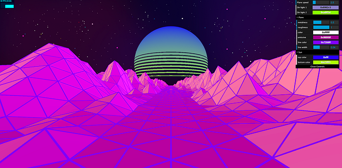
9. Add GUI controls to tweak params during runtime
GUI controls are useful for developers to test various param values quickly during runtime. Usually, GUI controls are added in a pretty early stage of development, but for the sake of the flow for this article, I’d rather explain all the important code first.
Make the following changes in index.js:
  async initScene() {
    ...

    // GUI
    const gui = new dat.GUI()

+   gui.add(guiOptions, "speed", 1, 10, 0.5).name('Plane speed')
+   gui.addColor(guiOptions, 'dirLightColor1').name('Dir light 1').onChange((val) => {
+     this.dirLight1.color.set(val)
+   })
+   gui.addColor(guiOptions, 'dirLightColor2').name('Dir light 2').onChange((val) => {
+     this.dirLight2.color.set(val)
+   })

+   let planeFolder = gui.addFolder(`Plane`)
+   planeFolder.add(guiOptions, "metalness", 0, 1, 0.05).onChange((val) => {
+     meshMaterial.metalness = val
+   })
+   planeFolder.add(guiOptions, "roughness", 0, 1, 0.05).onChange((val) => {
+     meshMaterial.roughness = val
+   })
+   planeFolder.addColor(guiOptions, 'meshColor').name('color').onChange((val) => {
+     meshMaterial.color.set(val)
+   })
+   planeFolder.addColor(guiOptions, 'meshEmissive').name('emissive').onChange((val) => {
+     meshMaterial.emissive.set(val)
+   })
+   planeFolder.addColor(guiOptions, 'lineColor').name('line color').onChange((val) => {
+     lineMaterial.color.set(val)
+   })
+   planeFolder.add(guiOptions, "lineWidth", 0, 0.1, 0.01).name('line width').onChange((val) => {
+     lineMaterial.linewidth = val
+   })

+   let sunFolder = gui.addFolder(`Sun`)
+   sunFolder.addColor(guiOptions, 'topColor').name('top color').onChange((val) => {
+     let clr = new THREE.Color(val)
+     uniforms.color_main.value = hexToRgb(clr.getHexString(), true)
+   })
+   sunFolder.addColor(guiOptions, 'bottomColor').name('bottom color').onChange((val) => {
+     let clr = new THREE.Color(val)
+     uniforms.color_accent.value = hexToRgb(clr.getHexString(), true)
+   })

    // Stats - show fps
    this.stats1 = new Stats()
    this.stats1.showPanel(0) // Panel 0 = fps
    this.stats1.domElement.style.cssText = "position:absolute;top:0px;left:0px;"
    this.container.appendChild(this.stats1.domElement)
  },
Now you can tweak the params and colors however you want!
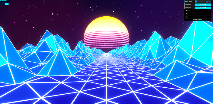
10. Post-process the scene with Bloom effect ✨✨ to make it look way cooler!
Here comes the final section of this article. We’re going to add the Bloom effect to light up the scene! This final touch is essential to make the scene look cool and emanate a synthwave vibe!
Make the following changes to index.js:
+ import { UnrealBloomPass } from "three/examples/jsm/postprocessing/UnrealBloomPass"

...

const params = {
  // general scene params
  speed: 2.5,
  dirLightColor1: 0x2dd7ff,
  dirLightColor2: 0x2dd7ff,
+ // bloom params
+ bloomStrength: 0.5,
+ bloomRadius: 0.2,
+ bloomThreshold: 0.5,
  // plane params
  metalness: 0.2,
  ...
}

...

// The RenderPass is already created in 'createComposer'
+ // Post-processing with Bloom effect
+ let bloomPass = new UnrealBloomPass(
+   new THREE.Vector2(window.innerWidth, window.innerHeight),
+   params.bloomStrength,
+   params.bloomRadius,
+   params.bloomThreshold
+ );
let composer = createComposer(renderer, scene, camera, (comp) => {
+   comp.addPass(bloomPass)
})

...

let app = {
  async initScene() {
  ...

    // GUI controls
    const gui = new dat.GUI()

+   let bloomFolder = gui.addFolder(`Bloom`)
+   bloomFolder.add(params, "bloomStrength", 0, 3, 0.05).onChange((val) => {
+     bloomPass.strength = Number(val)
+   })
+   bloomFolder.add(params, "bloomRadius", 0, 1, 0.05).onChange((val) => {
+     bloomPass.radius = Number(val)
+   })
+   bloomFolder.add(params, "bloomThreshold", 0, 1, 0.05).onChange((val) => {
+     bloomPass.threshold = Number(val)
+   })
It takes some experimenting to get the bloom parameters feel just right for the scene. With this final touch in place, the whole scene is now lit up ✨:
This is it. You have completed the tutorial!
To be honest, before writing, I had already built a version that I thought was good enough. However, when I started writing this article, I figured that it wasn’t good!
I was building the terrain geometry using a complicated custom BufferGeometry. The visuals and the performance were worse compared to the current result I have now. Thanks for reading.